Notes and Mathematica formulas for an initial greenhouse structure; description and pictures of final permanent structure decision. Final build completed in July 2018.
Christopher Clayton
07/26/2018
Summary of original design, final build and re-work into permanent structure - 6/23/2025
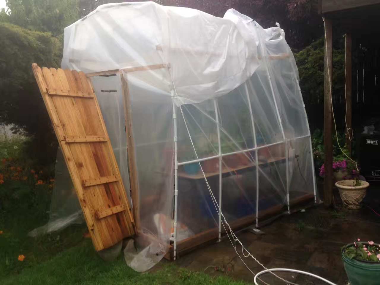
My original greenhouse project which utilized the Mathematica formulas and notes in the following section took place in 2016 as a PVC pipe and plastic sheet project, with a wooden rectangular base (not installed into a foundation) and a makeshift wooden door. This structure ultimately didn't hold well under south-to-north winds in the Pacific Northwest of the United States, especially with plastic connectors coming off that were meant to keep the plastic sheeting in place on the tubing. Below is the final image before tear-down where some of the wooden planks were displaced enough on their screws to eventually collapse the door frame on one side.
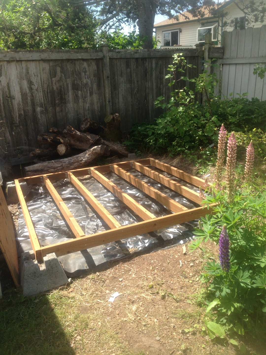
The next build attempt in 2018 consisted of creating an actual wooden stud beam-based floor frame on concrete corners that were leveled to the same height because of the sloped ground in that location of the yard. Then wooden boards were installed.
The wall build then consisted of spaced studs with thick wooden boards for an exterior and 45-degree cuts on the top. Then studs with 45-degree cuts on one side and a set amount of overhang on the other acted as the beams for a roof. The roof then consisted of hard, wavy plastic. The walls were filled with insulation and capped by an internal wall of meshed concrete.
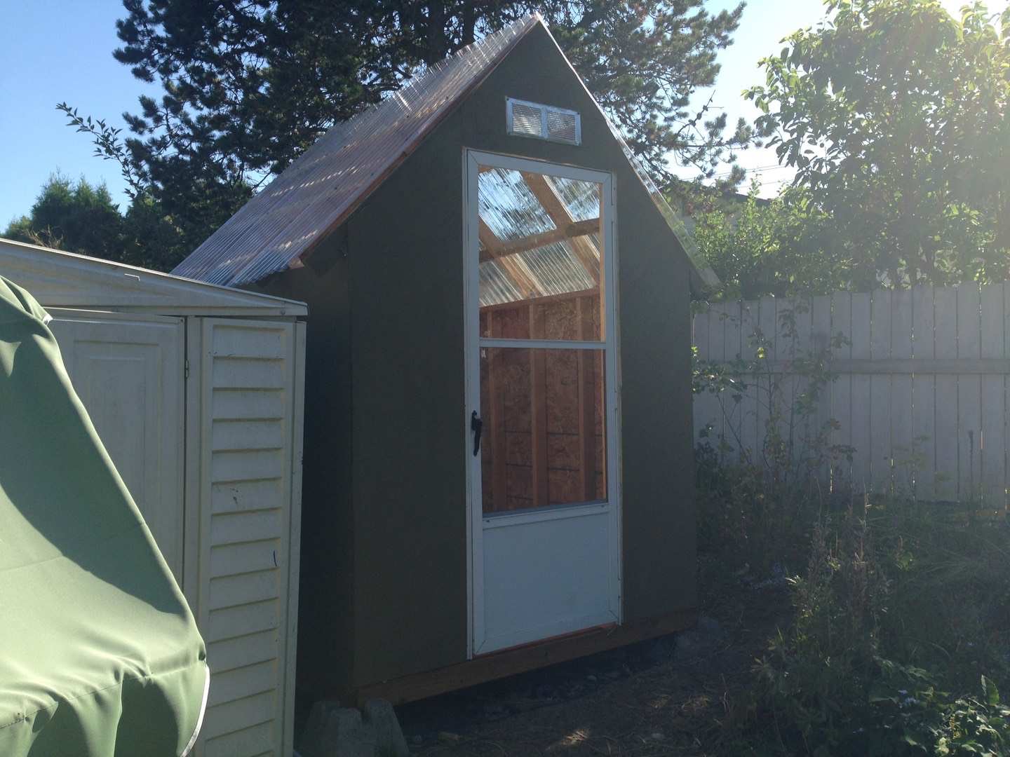
Ultimately, the roughly 6ft x 6ft x 8ft final permanent structure has consistently remained about 10 degrees Fahrenheit hotter than the outside. I keep a portable heater in it to maintain it at 60 degrees Fahrenheit in winter. The previous leaky all-plastic structure, needless to say, was not capable of that much warmth and the portable heater (same one still used in the permanent structure) was nearly constantly on in the winter. The heater under Pacific Northwest winter conditions in the permanent structure has consistently intermittently shut off from thermostat feedback for at least a few minutes at a time.
For this kind of permanent structure, the wooden outside walls and the internal concrete walls also needed a hole cut in for an electric socket. Conduit (more PVC piping) with wire was run from an external home electric socket to reach the greenhouse location.
Original design notes and formulas in Mathematica for what turned out to be a temporary plastic greenhouse structure from June 2016
Assuming 20' PVC pip stretched from one piece of rebar to another as attachments across 7 feet, we need to find the second diameter of this half - ellipse. The full ellipse will have perimeter = 40', and ' a' = 3.5 ft for radius 1 (length - wise radius).
The math is complicated for finding the perimeter of an ellipse, thus trying to solve for one of the radii to fit a certain perimeter will be even worse. So it's probably easiest to use a semi -circle and then get PVC cut to a smaller total length.
Therefore we have a semi - circle with a 3.5 ft radius, in this case. Therefore need to calculate pi (r) instead of 2 (pi) (r).
Pi*3.5 = 10.9956
Radius (width) needed to use 20 foot PVC in a semi - circular shape, which would also be half the maximum height.
20/3.1459265359 = 6.35743
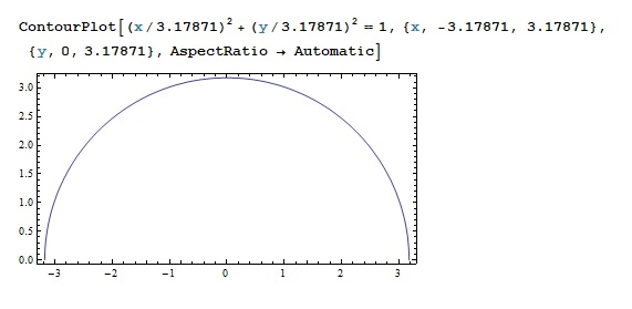
Radius (width) needed for 10 foot PVC in a semi - circular shape
10/3.1459265359 = 3.17871
XZ front view of 6.35742 ft width,
3.17871 ft height greenhouse semi - circle shape (thus a 10 ft half - circumference)
To get a reasonable height total, a 3 ft. high by 6.35742 wide rectangle shape needs to go underneath.
We want to make this 8 feet long with PVC or some other poles every 2 feet. Therefore need (due to the fence - post problem) -
2 two - by - four at 8 feet long
2 two - by - four at slightly under 6.35742 feet long to interface with the other pieces of wood 3 ten foot long tubes to be cut into ten 3 foot high pieces (5 on each side) to act as the rectangular supports.
5 ten foot long tubes to be cut into 10 five foot long pieces to be bent across in a semi - circle to attach to the ones facing upwards (5 on each side).
Need 6 quadruple T's for all of the three foot high tubes in the center
Need 4 triple T's for the front and back three foot high tubes on each side
Need 3 quadruple T's to connect the two sets of semi - circle - shaped tubes at the middle,
and 2 triple T's for the ends where the spine stops.
Need 1 ten foot tube to make into an eight foot spine.
Need 2 ten foot tubes to make into eight foot supports at the three - foot height level on each length - wise side.
Front and back will be supported by more two - by - four.
Width - wise two - by - fours need to be cut to roughly 6.10742 feet because an extra 1.5 inches (3 inches total, .25 ft) on each side represents the width of the connecting two - by - fours. So it actually should be fine to cut a clean 3 inches off of each one.
Also the boards could be placed further inward by .5 inches because that's the inner diameter of the PVC, and they will be placed on the outside of the length - wise boards.
So technically another whole inch needs to be cut off of each width - wise boards for 6.024086667 ft. So a total of 4 / 12 foot is taken off of the length - wise boards due to other objects' lengths finishing up where the semi - circle will end at 6.35742 ft.
Or if the tubes will land on the inside of the two - by - four, then they still need to be cut at 6.35 ft or so but I' m not seeing any designs that call for that.
The main type of tie that I'm thinking about is a PVC cross.
In this case we decided on 3/4 inch diameter for the piping too,
and will use conduit rather than PVC. In any case it's a four - way joint with all joints angled in the same way, and I can't find a triple - only version of it. So for the ends, we may need to use standard crosses and cap off the unconnected ends facing the outside.
Basic plastic film calculations -
10 ft x 8 ft length rectangular curved ceiling (the 10 ft. span across the 6.35 ft straight width) = 80 sq feet
2 areas of 3 x 8 = 48 sq ft. rectangular width - wise
pi (3.17871)^2 ft total for two semi circle (one whole circle = 31.743271895 sq ft. on front and back length - wise
2 areas of 3 x 6.35742 = 19.07226 sq ft. rectangular length – wise. Roughly 179 sq ft.
Probably need to aim for 200 sq. ft. of material in this case due to the semi - circular shapes.
Assuming the semi - circles are both rectangles instead - Two of 6.35742*3.17871 = 40.4167890564 ft which is not much of a bigger assumption anyway. Just adds 9 ft more to the total.
Subtracting the heights of the two - by - four board outer faces would be negligible, along with any boards for a front and back frame.
A door may be more significant in reducing film consumption, but it could be a roll - up door for these purposes.
We ended up with conduit lengths of 10.5 ft, at 1/2 inch with 3/4 inch knubs at the end.
Then they end up about 9.75 ft. if one cuts them in half, then puts one end inside the 3/4 inch end.
Therefore we're going to use 1/2 inch extra pieces to put at the knubby end instead,
then put the PVC crosses in those to make for approximately 10 - foot ceiling ribs. Also the 8 - foot spine running through it will need to be cut into multiple pieces because it most likely won't be able to run straight through the PVC crosses.
The total length of the ribs can be adjusted more accurately to 10 ft each by twisting sections into the connecting cross further in or out.
Also 10 pieces of 10 mm by 3 ft rebar (or some diameter like that) do need to go into the straight pieces so they don't bend at the top. Then they can be end - capped with some kind of PVC cap to keep the rebar in, if it is not to be staked into the ground.
Or the other idea is some kind of a rubber cap.
The half - fasteners for the ends are metal (probably to make up for lack of rigidity) and even though rated correctly for 1/2 - inch conduit, had to be hammered to make them fit around.
These 5 - feet conduit pieces will not bend like a quarter circle at all - they bend extremely and then taper off such that they put a lot of stress at the base.
So on one end we are going to add 90 degree curve conduit which will increase the total length of conduit and also not make it a semi - circle, but will retain even more height and make for a gentler slope.
We could try to connect the 90 degree curves directly to a spine but then it may generate a slight S - curve in the middle of each side.
So we may need more straight pieces coming out of the 90 degree curves and not try to explicitly bend any conduit at all.
Ideally it would be 45 or 30 degrees so it may need to be 1/2 inch piping instead. That would allow for a pre - bent curve to ease the straight 5 - foot conduit into a gentler curve, and overall approximate a semi - circle better.
We did use 45 degree PVC curves, then put extra 22.25 inch conduit pieces onto them to connect to PVC crosses in the middle for the spine.
So the total height is actually 8.5 ft due to the smaller curvature (trapezoid - like shape).
8*6.3 ceiling = 50.4 sq. ft
2 front faces of 6.3*8.5 after approximating that the top faces are big rectangles = 107.1 sq. ft
2 lower faces of 3 * 8 = 48 sq. ft. = 205.5 sq ft.
So this has increased in square area from the original.
Right now it is just triple PVC connectors at the corners but the corners at the ends of the straight 3 - ft. sections could be corner quads to allow for a back - brace. However we only found corner triple connectors at Home Depot, with one end threaded.
Apparently when painted, the extra 1/2 inch of 1/2 inch diameter conduit sticking out of the 3/4 inch bulbs on one side did not connect very well to the schedule 40 PVC.
So dad cut off those bulbs so we didn't have to do all of those indirect connection techniques.
So that probably lowered one side by 1/2 an inch in length to 4.5 feet at the top portion,
then the side without end - bulbs was cut by 1/2 an inch in length to compensate.
So it just got a little lower but it's already higher than I thought it would be anyway.